BrunDog:
After seeing your impressive level of automation via homebrewtalk.com, I started designing my system from scratch, as I have nothing brewing related. One of the significant insights you provided was to put the kettle ports on the bottom. Why didn't I think of that?
I'm planning on using BRUCONTROL as part of my overall design and therefore want to purchase control hardware (motors, electrical valves, sensors, etc) compatible with it. Does a BRUCONTROL license come with a list of the hardware you've successfully used? I don't want to reinvent the wheel.
Hi RoatanBill,
Thank you for the inquiry and compliment! I think bottom drain is the only way to go, and honestly don't understand why more kettle manufacturers don't offer it as a default option. One of the problems is their kettles were made for flame (or induction) so have tri-clad, aka thick, bottoms. You don't want to drill through that. But since I used cheap Bayou Classic stock pots, I didn't sweat it. I recommend to either solder on couplings (I used the ones from McMaster-Carr which have a pretty good surface area to them, or a spud like these: https://www.brewhardware.com/product_p/spud.htm or pull through solderable like these: https://www.brewhardware.com/product_p/ptbulkhead.htm. Doing this with an automated setup allows for automated cleaning with clean-in-place (CIP), which makes cleaning a bit easier.
This website is new, and we have been working on getting the videos done... now that it is, we will be posting up some shopping lists, etc. That, and any other advice is free. You just pay for the software license! Thanks and good luck with your build - let us know how we can help.
I want to get to your level of automation, so I'd like to know if I've identified all the holes in the kettles for all the normal hose and electrical connections as well as the unique ports like a pressure sensor that you use. I believe I've identified a way to put almost all the ports through the bottom of the kettle so I can conveniently insulate them. I'm going to weld up a custom stand to support this arrangement. I see no way to upload my CAD drawings, so here are the descriptions.
HLT - 2 bottom ports for circulating water pump, 2 bottom ports for HERMS coil, 1 bottom port for pressure sensor and one large side port for the heating element.
MLT - 1 bottom and one top side port for connection to HERMS coil, 1 bottom port for pressure sensor.
BK - 2 bottom ports for whirlpool pump & drain, 1 bottom port for pressure sensor and one large side port for the heating element.
3 way valves will allow for interconnecting kettles as needed. Temp sensors are in the plumbing lines. No sight glasses. Should I be considering any other sensors/ports?
Hi RoatanBill,
If you have CAD drawings, it would be helpful. Obviously you are going to automate the temperature control. I assume pump control. Do you want to automate the valves also? If so, what about incoming water? What about flush water for the chiller (assuming plate or counterflow). A full list of details/drawings would be helpful. If you are going to automate the valves, you should plan out the valves (either 2-way or 3-way) as best you can to perform all the switching you want. I can draw something up for you but it would help to have the details first.
Yes, I have drawings, but I see no way to upload them to your site. As I type this, I see the available controls, and none appear to offer a file upload.
I'm a Linux guy since 2000 and use a Linux CAD application (CYCAS) so the best I can upload would be a screen capture (jpg). I have one Windows 10 box that I use for Windows specific apps, and your BruControl would be one of them, but I'd probably dedicate a box to BruControl.
There was a limited number of posts you needed to make before uploading. You should be able to do it now.
Alternatively, email to info [at] brucontrol.com.
Water will dribble into the HLT from a reverse osmosis system. All water here is well water so a filter is needed for everything. I want to automate temperature control, the gross movement of liquids using the pressure sensors and pumps, and also some DC motors that will raise and lower the kettles.
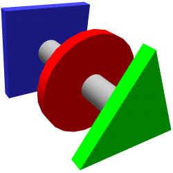
Although you can't see it in the 3D rendering, the kettles will tilt forward for easy in place cleaning. I want to use gravity (no pump) for sparge by raising up the HLT so that water will gently flow into the MLT using the pressure sensors for control. Same goes for filling the BK; lower the BK, and raise the MLT so that gravity can gently pull wort from the MLT without a pump. For chilling, raise the BK above the counterflow chiller and let gravity take it's time to empty it. These are experiments I want to run. I can always use pumps if necessary.
As I've never brewed before, I can't plan out the valve arrangements due to ignorance. Up front, I'll provide manual hose movements till I thoroughly understand the process and add valve automation later. Every port will immediately go to a standard valve to start with. I see that I can only add one file here, so I'll email the rest. I've also drawn up miniature 10G (2 5G kegs) fermentation vessels that are stackable in a rack to save floor space with an integrated 30G chill water supply where each 10G unit has its own temperature selection. I have yet to draw up a keg serving unit.
I'll MIG and TIG weld up everything and plan on using spray in foam for insulation. I suspect I'll use 1/2" Neoprene to insulate the kettles as I can't find anyone that will sell me a small quantity of Aerocel sheet goods. I wanted as many ports on the bottom as possible to provide a clean surface to insulate and remove the long moment arms that the valve assemblies represent in the normal arrangement.
Lots of ways to skin a cat!! Very cool ideas here. Certainly not a trivial undertaking, and I strongly echo your sentiment to do it in stages. I have learned that many ideas I had didn't pan out as expected and I needed to make changes. You don't want to go too far down a rabbit hole then realize it will be a huge effort (and expense) to climb back out.
The motors are intriguing, and gravity never fails - so you can do this over pumps, though I do wonder if the motors/slides (bearings, etc.) will be more of an undertaking than just pumping your liquids. Should you do this though, we have to consider how you will control the motors/positioning. We don't currently have motor control built into the system, but this is something on the roadmap. I imagine we could do simple motor ON/OFF with either a digital input to assess position with a simple encoder. Or we could do it with the pressure sensors as you mentioned, though we might need faster response out of them than is typically needed.
The motors to lift the kettles are chain coupled to 3/4" acme thread screws that will raise them up at about 12"/minute depending on the large sprocket I chose versus the small one already on the motor. Since the motors are 24VDC, I could also throttle them up or down and then set them at some specific point outside of the control loops and just do turn on/off which is simple. At such slow speeds, any latency in sensors is negligible (I hope). The screw sits on a bearing that transfers the weight to the stationary spine.
The spine on the drawing is actually square tube inside square tube with about 1/16" clearance all around. I may not need bearings, but if I do, I can set them up so the tubes don't contact each other. This would eliminate drag, but the motors I have in mind are plenty powerful. I don't envision requiring sensing motor position, only water pressure. Pressure will indicate to raise or lower the platforms.
